

 العربية
 English
 français
 Deutsch
 español
 中文
中文
كيفية حساب THD وPF?
تحليل التشوه التوافقي الكلي (THD) وتقييم عامل القدرة ضمن هذه المناقشة، سنستكشف منهجيات لقياس التشوه التوافقي الكلي جنبًا إلى جنب مع حسابات عامل القدرة.
التشويه التوافقي الكلي (THD) هو مقياس يعكس دمج الترددات التوافقية المتجاورة مقابل التردد الأساسي - مثل 60 هرتز - في الدائرة. ويشمل جميع الترددات التوافقية الموجودة. يمكن أن يرتبط THD بتوافقيات التيار أو الجهد. لقياس التشوه في خط الجهد، قم بتطبيق الصيغة التالية:

الشكل 1. يجب إجراء قياس THD عند المحول، وليس بالقرب من الحمل.
حيث Vn_rms هو جهد RMS للتوافقي n، ويشير Vfund_rms إلى جهد RMS للتردد الأساسي. موجة جيبية نقية، خالية من التوافقيات العالية، مثل مصدر جهد لا تشوبه شائبة، تعرض THD بنسبة 0%. تشير أي قيمة THD تتجاوز الصفر إلى تشويه الموجة الجيبية. يتم عادةً عرض أرقام THD كنسب مئوية، على سبيل المثال، 5% أو 50%. يمكن تقييم THD لكل من إشارات التيار والجهد.
تنشأ التيارات التوافقية من الأحمال غير الخطية التي تسحب التيار في نبضات. تنبع توافقيات الجهد من مرور هذه التيارات عبر مقاومات النظام المتنوعة. يؤدي تيار المحول إلى انخفاض الجهد عبر ملفاته. عندما ينبض التيار، يعكس الجهد هذا النبض. يعد تشويه الجهد الزائد ضارًا لأنه يعمل كقناة للتوافقيات تجاه الأحمال الخطية، مثل المحركات الكهربائية. تقدم توافقيات الجهد تسخينًا إضافيًا في أنظمة توزيع الطاقة والأجهزة المتصلة.
في استكشاف أخطاء الدوائر التوافقية وإصلاحها، تأكد من قياس كل من الجهد THD والتيار THD. تضمن النتائج المثالية عدم تجاوز الجهد THD بنسبة 5%، وبقاء THD الحالي أقل من 20% من التردد الأساسي. يجب تقييم THD على مستوى المحول لإجراء حساب دقيق لـ THD على مستوى النظام (كما هو موضح في الرسم التوضيحي 1). توفر قراءات THD من جانب التحميل أعلى القيم نظرًا لعدم حدوث الإلغاء التوافقي في جميع أنحاء النظام.
عند قياس تيار THD في ظل ظروف الحمل الكامل، فإن THD يشبه تشويه الطلب الإجمالي (TDD). TDD هو حاصل التوافقيات الحالية لتيار الحمل النهائي. يتم تنفيذ قياس THD عند تشخيص الأنظمة أو اختبارها. يختلف TDD عن THD لأنه يتم قياس TDD مقابل قياس الذروة الحالي بمرور الوقت. THD يقيس التيار فقط في لحظة القياس. يتمثل دور TDD في حساب الحالات التي يكون فيها THD مرتفعًا، ومع ذلك يكون الحمل الإجمالي منخفضًا نسبيًا. في ظل هذه الظروف، يكون TDD متواضعًا، مما يقلل من ارتفاع درجة الحرارة.
Power factor delineates the ratio of authentic power to apparent power in a circuit or distribution network. Every AC circuit is comprised of real, reactive, harmonic, and apparent (aggregate) power. True power, in watts or kilowatts, is expended by motors, lighting, and other apparatuses to execute functional tasks. Reactive power, in volt-amperes reactive or kilovolt-amperes reactive, is stored and discharged by inductors and capacitors. Reactive power materializes as phase displacement between current and voltage waveforms. Harmonic power, in volt-amperes or kilovolt-amperes, is dissipated due to harmonic distortion. Apparent power, in volt-amperes or kilovolt-amperes, is the vectorial sum of true power, reactive power, and harmonic power. Apparent power isn't a simple accumulation but a vector summation.
Displacement Power Factor
The displacement power factor is the ratio of genuine power to apparent power attributable to phase displacement between current and voltage (as shown in Illustration 2). Capacitors can frequently be integrated into a circuit or distribution network to rectify the displacement power factor. Its computation is as follows:
PF = cos(θ)
where PF signifies displacement power factor and θ is the discrepancy between voltage and current phases in degrees. Note: DPF or PFD may occasionally substitute PF to denote displacement power factor.

Figure 2. Displacement power factor enables calculation of the power genuinely accessible for a load.
The presence of harmonics introduces complexity into the discussion of power factor. The distortion power factor, defined as the ratio of true power to apparent power due to Total Harmonic Distortion (THD), cannot be mitigated simply by adding capacitors to a circuit. This is because the impedance of capacitors decreases with an increase in frequency, potentially turning them into sinks for high-frequency harmonics rather than effective compensators.
To address the distortion power factor, specialized solutions are employed. These include special types of transformers designed to handle harmonic loads or tuned harmonic filters that consist of a combination of capacitors and inductors. Such filters are specifically engineered to resonate at harmonic frequencies, effectively absorbing or cancelling out these distortions.
The calculation of the distortion power factor involves assessing the impact of harmonic content on the overall power factor, reflecting the diminished efficiency caused by the presence of these higher-order frequencies in the electrical system.
The distortion power factor is calculated as follows:
.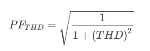
where
PFTHD = distortion power factor
THD = total harmonic distortion
The total power factor is the product of the displacement power factor and the distortion power factor and is calculated as follows:
PFTot = PF × PFTHD
where
PFTot = total power factor
PF = displacement power factor
PFTHD = distortion power factor
For example, what is the total power factor when the displacement between voltage and current is 25°, and the THD is 49% (0.49)? The displacement power factor is calculated as follows:
PF = cos(θ)
PF = cos (25°)
PF = 0.906
The distortion power factor is calculated as follows:
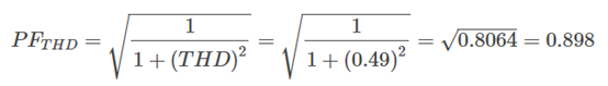 .
.
The total power factor is calculated as follows:
PFTot = PF × PFTHD
PFTot = 0.906 × 0.898
PFTot = 0.814
Understanding the total power factor is crucial as it directly correlates with apparent power, which is fundamental in sizing components within a power distribution system. Apparent power serves as a key metric for ensuring that all elements in the system are appropriately rated to handle the electrical load without being overloaded.
Current Crest Factor
The current crest factor, defined as the ratio of the waveform's peak value to its RMS value, serves to indicate the extent of distortion in the waveform. Its calculation provides insights into the waveform's quality, with higher factors pointing to greater levels of distortion. The formula for determining the current crest factor is as follows:
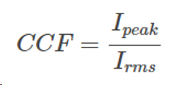 .
.
where
CCF = current crest factor
Ipeak = peak value (in A)
Irms = root mean square value (in A)
For example, what is the current crest value of a perfect sine waveform? In a perfect sine waveform with a peak value of 1, the rms value is 0.707.
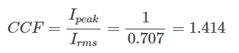 .
.
An elevated current crest factor can result in excessive heat generation within circuits and devices. For instance, on a 120V circuit powering digital equipment such as computers, a distorted current waveform might display a crest factor ranging from 2 to 6 (consult Figure 3). Typically, circuits with a higher current crest factor contain a greater proportion of energy in their higher harmonics.
A power source is obligated to provide the peak power needed by the circuit, matching the specified voltage and current demands. A conventional backup power system, such as an uninterruptible power supply for computers, is capable of delivering a current crest factor of 3 when operating at full capacity but may experience augmented crest factors under lighter load conditions.

Figure 3. The current crest factor comparison
Source Impedance
تؤثر مقاومة المصدر على عامل القمة الناتج عن الأحمال غير الخطية. عند الوصول إلى عتبة جهد محددة، يبدأ مصدر الطاقة في شحن مكثف التنعيم. عندما تكون مقاومة المصدر في حدها الأدنى، يكون تدفق التيار إلى المكثف كبيرًا، مما يؤدي إلى مدة شحن قصيرة. على العكس من ذلك، فإن الممانعة الأعلى تحد من تدفق التيار، وبالتالي تطيل فترة شحن المكثف. تعمل فترة الشحن الطويلة هذه على تقليل عامل القمة بشكل فعال. يمكن للمرء زيادة مقاومة المصدر من خلال دمج مفاعلات خطية أو محولات عزل المحرك.


 دعم شبكة IPv6