

 العربية
 English
 français
 Deutsch
 español
 中文
中文
يمكن لورشة إصلاح هياكل السيارات تشغيل مئات نقاط اللحام في الدقيقة، بينما تتغير احتياجات الروبوتات والمكابس والناقلات وخطوط الطلاء وأنظمة التكييف والتهوية من الطاقة الكهربائية باستمرار. قد يبدو خط الإنتاج مستقرًا ميكانيكيًا، لكن الحمل الكهربائي الذي يتعرض له المحول ليس كذلك. قد تظهر تغيرات سريعة في القدرة التفاعلية، وانخفاض معامل القدرة، وتقلبات الجهد، والتيار التوافقي عند بدء تشغيل عدة محولات لحام أو محركات في الوقت نفسه.
بالنسبة لمصنعي السيارات، لا تقتصر المشكلة على فاتورة الكهرباء فحسب. فقد تتسبب رداءة جودة الطاقة في انقطاعات في عمليات اللحام، وتعطل أنظمة الحماية بشكل غير متوقع، وارتفاع درجة حرارة المحولات والكابلات، وعدم استقرار تشغيل أنظمة التحكم الآلي الحساسة. تشرح هذه المقالة أهمية نظام التعويض الهجين الذي يجمع بين...مولد القدرة التفاعلية الثابتة(SVG) مع المكثفات التي يتم تبديلها بواسطة الثايرستور (TSC) يمكن أن يكون أكثر عملية من بنك المكثفات وحده للأحمال الصناعية سريعة التغير.
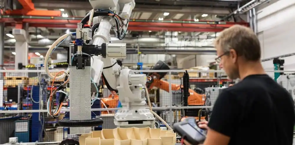
الشكل 1. سياق تطبيق أتمتة تصنيع السيارات وجودة الطاقة.
تجمع مصانع السيارات بين أحمال ثلاثية الطور ثابتة وأحمال نابضة ومتغيرة بسرعة. تتطلب آلات اللحام المقاوم تيارًا عاليًا لفترات قصيرة. تُغير محركات المؤازرة ووحدات التحكم في الروبوتات السرعة وعزم الدوران مع تغير تسلسل الإنتاج. تُضيف المراوح الكبيرة والمضخات والمبردات والناقلات طلبًا حثيًا، بينما تُساهم أنظمة التحكم ومصادر الطاقة في التيار التوافقي.
قد يسحب محول اللحام تيارًا تفاعليًا كبيرًا خلال دورة لحام قصيرة. عند تشغيل عدة مسدسات لحام متتالية، يشهد ناقل الشبكة تغيرًا حادًا بدلًا من منحنى حمل سلس. إذا كان نظام التعويض بطيئًا، ينخفض معامل القدرة قبل أن تتمكن خطوة المكثف التالية من التبديل. قد ينتج عن ذلك تذبذب في الجهد، ووميض، وتيار إضافي في خط التغذية.
قد تُظهر بيانات الطاقة الشهرية متوسط معامل قدرة مقبولًا بينما لا يزال خط الإنتاج يعاني من اضطرابات قصيرة الأمد. وتُخفي قيم متوسط استهلاك الطاقة (كيلوواط) ومتوسط القدرة التفاعلية (كيلوفار) الأحداث التي تُسبب إنذارًا في وحدة تحكم الروبوت أو تشغيل مرحل الحماية. لذا، ينبغي على المهندسين مراجعة قياسات السلاسل الزمنية عند نقطة الربط المشتركة، وليس فقط فاتورة الكهرباء.
توفر بنوك المكثفات التقليدية القدرة التفاعلية على مراحل منفصلة. وهي تعمل بكفاءة عندما يتغير الحمل ببطء وتكون مقاومة النظام قابلة للتنبؤ. لكن مصانع السيارات لا تستوفي هذه الشروط دائمًا. فقد يتغير طلب خط اللحام على القدرة التفاعلية أسرع من استجابة بنك المكثفات المُشغَّل بواسطة موصل، كما يمكن للتيار التوافقي أن يتفاعل مع بنك المكثفات مُحدثًا حالة رنين غير مرغوب فيها.
للمكثفات حد أدنى عملي: لكل خطوة حجم ثابت. إذا كان التعويض المطلوب يقع بين خطوتين، فقد يُعاني النظام من نقص أو زيادة في التعويض. قد تؤدي الزيادة في التعويض إلى زيادة معامل القدرة، مما يزيد من مخاطر الجهد؛ بينما يُعرّض نقص التعويض المحطة لغرامات من شركة الكهرباء وتيار تغذية غير ضروري.
يجمع النظام الهجين بين وظيفتين متكاملتين. يوفر قسم TSC تعويضًا تفاعليًا ذا سعة أكبر على مراحل، بينما يوفر SVG ضبطًا دقيقًا مستمرًا ويستجيب للتغيرات السريعة. ينسق نظام التحكم كلا القسمين بحيث يتعامل SVG مع الانحرافات السريعة والصغيرة، بينما توفر مجموعات المكثفات المحولة دعمًا فعالًا للجهد الكلي.
يستخدم جهاز SVG عاكس مصدر الجهد لحقن أو امتصاص التيار التفاعلي وفقًا لحالة ناقل الشبكة المقاسة. ويمكنه تصحيح كل من القدرة التفاعلية المتأخرة والمتقدمة ضمن نطاق التشغيل المحدد. يقلل هذا التحكم المستمر من النطاق الميت الذي يحدث بين خطوات المكثف، ويساعد على استقرار معامل القدرة أثناء دورات اللحام وتسارع المحرك.
تُعدّ مجموعات TSC مفيدةً عندما يتطلب المصنع كميةً كبيرةً من القدرة التفاعلية الثابتة أو المتغيرة ببطء. يستطيع جهاز التحكم تبديل مجموعات المكثفات المناسبة بينما يتولى SVG إدارة الخطأ المتبقي. يُمكن لهذا المزيج تقليل سعة المحول المستمرة المطلوبة مع الحفاظ على الأداء الديناميكي السريع. يتطلب تحديد حجم خطوة TSC وجهاز التبديل وتسلسل التحكم تصميمًا خاصًا بالموقع.
| العامل الهندسي | بنك المكثفات التقليدي | SVG | SVG هجين + TSC |
|---|---|---|---|
| التعويض التفاعلي | خطا | مستمر | التحكم الدقيق المتدرج بالإضافة إلى التحكم الدقيق المستمر |
| الاستجابة لدورات اللحام | محدود بسبب تأخير التبديل | استجابة ديناميكية سريعة | يدعم SVG التغييرات السريعة؛ بينما يدعم TSC التغييرات الكبيرة في kvar |
| التحكم المتقدم / المتأخر | عادة ما يكون محدودًا بالتكوين | ثنائي الاتجاه ضمن التصنيف | تحكم ديناميكي في SVG مع دعم TSC |
| التفاعل التوافقي | يتطلب خطر الرنين دراسة | التحكم الإلكتروني الفعال للطاقة | يتطلب ذلك دراسة منسقة للتوافقيات والرنين |
| استقرار معامل القدرة | يمكن أن يتأرجح بين الخطوات | ضبط سلس | ضبط سلس مع حجم محول أصغر |
| الأنسب | أحمال بطيئة ومستقرة | الأحمال الديناميكية السريعة | محطات كبيرة ذات طلب كبير وديناميكي على الكيلوفار |
المصفوفة التالية هي مرجع هندسي أولي. يجب أن يعتمد تحديد الحجم النهائي على بيانات الحمل المقاسة، ودورة تشغيل اللحام، وسعة المحول، ومستوى الجهد، والطيف التوافقي، وأداء نقطة التوصيل المشتركة المطلوب.
| حالة النبات | أعراض كهربائية نموذجية | أولوية القياس | اتجاه الحل الأولي |
|---|---|---|---|
| ورشة إصلاح هياكل السيارات مزودة بالعديد من ماكينات اللحام النقطي | تقلبات kvar سريعة وميض الجهد | اتجاه القدرة التفاعلية (kvar)، تقلبات الجهد، دورة تشغيل اللحام | تقييم استجابة SVG وقدرة SVG + TSC الهجينة |
| خط تجميع آلي | إنذارات المؤازرة أثناء بدء التشغيل المتزامن | أحداث الجهد، تيار الطور، الطوابع الزمنية للأحداث | تحقق من دعم الجهد الديناميكي ومعاوقة المغذي |
| ورشة طلاء ونظام تكييف الهواء | معامل القدرة المنخفض أثناء ارتفاع الطلب على التبريد | كيلوواط، كيلوفار، ومعامل القدرة حسب الوردية والموسم | استخدم دعم TSC المجمع مع ضبط دقيق لملفات SVG |
| توسيع المصنع | لا يمكن للبنك الحالي اتباع النهج الجديد | جدول الأحمال المستقبلية وسعة المحول الاحتياطية | حجز مساحة معيارية وتنسيق استراتيجية التحكم |
| محركات توليد التوافقيات | ارتفاع درجة حرارة المكثف أو انقطاع التيار الكهربائي بشكل مزعج | طيف THD ومسح الرنين | قم بتقييم APF بالإضافة إلى SVG/HPFC عند الاقتضاء |
ابدأ بخطة قياس بدلاً من تقييم المنتج. سجّل الجهد والتيار والطاقة الفعّالة والطاقة غير الفعّالة ومعامل القدرة والتشويه التوافقي الكلي (THDi) ورتب التوافقيات الفردية عند ناقل الطاقة الرئيسي ومغذيات الإنتاج ذات الصلة. سجّل عدة حالات إنتاجية: بدء تشغيل الخط، والتشغيل العادي، وتغيير الورديات، وذروة نشاط اللحام، وذروة الطلب على أنظمة التدفئة والتهوية وتكييف الهواء.
ثم راجع بيئة التركيب. تأكد من الجهد المقنن، والتردد، ومستوى قصر الدائرة، ومساحة اللوحة، والتهوية، ودرجة الحرارة المحيطة، ومسار الكابلات، وموقع محول التيار، ومتطلبات الاتصال. يتطلب النظام الهجين أيضًا التنسيق بين وحدة تحكم SVG وتسلسل تبديل TSC - وهو موضوع تكوين تم تناوله في YT Electricحلول المعوض فار الهجينقد يؤدي سوء تحديد موقع التصوير المقطعي المحوسب أو تسلسل الطور غير الصحيح إلى تقليل قيمة المعدات المناسبة في الأحوال العادية.
شركة YT Electricمولد طاقة ثابت هجينيجمع هذا التصميم المعماري بين مولد إشارة متطور (SVG) وتعويض مكثف التبديل أو المفاعل وفقًا لمتطلبات الموقع. وتصف معلومات المنتج الخاصة بالشركة النظام الهجين بأنه مزيج من تعويض مولد الإشارة المستمر ودعم محول التيار المتردد المتدرج (TSC)، مع خيارات تركيب معيارية وتنسيق تحكم خاص بالموقع.
بالنسبة للطرازات المناسبة، تتضمن بيانات المنتج المنشورة بنية ثلاثية المستويات، وخيارات جهد مقنن 400 فولت، وقدرات خزانة تتراوح من 100 كيلو فار إلى 500 كيلو فار، وتردد تبديل/تحكم ASVG يبلغ 25.6 كيلو هرتز، وزمن استجابة SVG يصل إلى 5 مللي ثانية. تنطبق هذه القيم على تكوين المنتج ذي الصلة، ويجب التحقق منها وفقًا للطراز المختار وظروف المشروع.
قد يكون هذا الخيار أنسب عندما يكون لدى المحطة طلب كبير على الطاقة التفاعلية بكميات كبيرة وتغيرات سريعة في قيمة kvar. يوفر نظام SVG تصحيحًا مستمرًا، بينما توفر مجموعات TSC سعةً متدرجةً للطاقة التفاعلية بكميات كبيرة. يتطلب القرار النهائي إجراء قياسات ودراسة توافقية/رنينية.
قد يدعم قسم SVG واستراتيجية التحكم تعويض التوافقيات في التكوينات المناسبة، ولكن يجب التأكد من أداء التوافقيات المطلوب من مواصفات المنتج ودراسة الموقع. إذا كان تيار التوافقيات هو المشكلة الرئيسية، فقم بتقييممرشح الطاقة النشط (APF)أو حل يجمع بين APF و SVG.
لا تعتمد في تحديد حجم النظام على قدرة المحول بالكيلوفولت أمبير فقط. استخدم قياسات تقلبات القدرة التفاعلية بالكيلوفولت أمبير، ودورة تشغيل اللحام، ومعامل القدرة المستهدف، ومستوى الجهد، والطيف التوافقي، وخطط التوسع الإنتاجي المستقبلية. يمكن لشركة YT Electric استخدام هذه البيانات لإعداد توصية خاصة بالتطبيق.
تستخدم بعض أنظمة YT Electric تصميمات معيارية، لكن التوسع يعتمد على تصميم الخزانة، وهيكل التحكم، ونطاق محولات التيار، وسعة ناقل البيانات، ومساحة التركيب المخصصة. تأكد من خطة التوسع قبل تقديم الطلب الأول.
تفرض صناعة السيارات متطلبات غير اعتيادية على الأنظمة الكهربائية، إذ تتغير احتياجات الطاقة لأنظمة اللحام والروبوتات والمحركات وأنظمة التكييف والتهوية والناقلات بسرعات متفاوتة. وقد يؤدي استخدام مجموعة مكثفات فقط إلى فجوة بين التعويض الأساسي والتغيرات السريعة العابرة التي تؤثر على الإنتاج.
يمكن لنظام SVG + TSC الهجين المنسق أن يجمع بين دعم القدرة التفاعلية (kvar) بكميات كبيرة وبتكلفة اقتصادية مع تصحيح ديناميكي مستمر. بالنسبة للمواقع التي تشهد تيارات توافقية كبيرة، ينبغي على المهندسين إضافة تقييم APF بدلاً من افتراض أن تعويض القدرة التفاعلية يحل جميع مشاكل جودة الطاقة.
اتصل بشركة YT Electric لإجراء تقييم لجودة الطاقة في صناعة السيارات، ومراجعة اختيار نظام SVG + TSC الهجين، والحصول على عرض أسعار خاص بالمشروع.



 دعم شبكة IPv6